Pixel perfect
Barbara Lamb explores the issues that need to be considered in producing high-quality digital images in dental practice
For many years, dental practices have been working with X-ray film and the associated processing chemicals. Quality assurance was well documented and was taught to undergraduate dental students and dental care professionals in training.
Ongoing continuing professional development of the dental team clarified how to deal with processing problems and so, over many years, the quality assurance of film images has improved with education. Digital imaging, with technology advancing in dental practices, has become more and more popular and a growing number of practices now work with digital systems.
Quality assurance in relation to monitors to view images and how to recognise and correct errors in the digital image production should now be part of a practice’s quality assurance programme. This aims to produce consistently high-quality images while keeping doses as low as reasonably practicable (ALARP). Practice quality assurance should be documented and audited.
Many dental practices have made the move to digital imaging, but not all dentists are happy with the resulting images. The two parts of this article seek to assist understanding of the issues concerned. The first part looks at some of the problems dental practices experience in recognising the problems with the resulting image and at possible ways to rectify them and the second part looks at the role computer systems can have in relation to the optimisation of digital images.
There are two types of digital image receptor, both of which capture a two-dimensional image of the three-dimensional patient. These are computed radiography (CR) photostimulable phosphor plates (PSPs) and direct digital radiography (DR) solid-state detectors (SSDs).
There are approximately 256 shades of grey pixels, which together make up the finished digital image. The sensors are very sensitive to X-rays and so the exposure to the patient can sometimes be dramatically reduced compared to that used with conventional radiographic emulsion film.
Photostimulable phosphor plates
Under a protection layer is a photosensitive phosphor plate (PSP). This absorbs and stores the X-ray energy.
After exposure, the plate is placed in a processor where it is scanned and the energy is released as light. This is detected by a photomultiplier and the image divided into pixels. A photomultiplier gives them a numerical value in relation to the intensity of the light released and the digital information is stored in the computer. The image can then be manipulated and displayed.
PSPs are comparable in size to a conventional X-ray film and are compatible with most film holders. They are patient friendly and are suitable for use on most individuals including children and elderly patients. The more radiation that hits the sensor the darker the image will be.
The capturing of the image is not instant, but it takes only a matter of seconds rather than the few minutes it takes to process an emulsion film. After the plate has been scanned, the latent (invisible) image is then cleared by being exposed to light, either in the scanner or, less often nowadays, manually on a light box.
Quality Assurance for PSPs
1. Surface marking
The phosphor layer is delicate and very easily marked by any form of rough handling. All staff who handle PSPs should be aware that they must not bend or scratch them, since even normal handling can damage the surface. This marking can degrade the image significantly and is irreversible for any future image production.
If the scanning system does not have an integral white light clearer, then the plates should be placed on an X-ray viewing box to erase the latent image. Problems can occur when the plate is lifted off after clearing. If the plate is slid across the surface of the box, the plate can be scratched (Fig 1). To minimise the possibility of this occurring, the box can be covered with cling film or see-through bubble wrap, allowing the plate to be lifted off rather than slid across the surface.
Custom-made mats are available that resemble a rubber bubble wrap on which the plate can be placed prior to and after scanning, allowing the plate to be lifted off any work surface without scratching.
To ensure that PSPs are not marked beyond what is acceptable for image reading, the serial number should be taken and regular checks should be done to monitor for marks. To do this, the plate should be placed on a surface in its protective packet. No step wedge should be used.
Next, the spacer cone should be lined up with the plate at a distance of 20cm (the usual focal skin distance used in parallelling technique). The exposure given is very small (tiny flash exposure) and, when scanned, any marks will be visible. Each surgery should be responsible for its own plates. The time frame between these checks will vary in relation to the number of images captured and the quality of sensor handling by the staff.
2. Fogging limitation
As the PSPs are very sensitive to radiation, even background radiation can base fog them. To limit this, the plate should be cleared every day by placing on a light box for a few minutes before use. If this is done in the morning, the plate should be fine until the end of the day.
Once again, to avoid marking, cling film can be stretched over the viewing box or see-through bubble wrap placed on the box before placing the sensors, blue side down, on the surface to clear. Alternatively, if the scanner has an integral light clearer, the sensors can be cleared first thing every morning in the scanner.
3. Sensor positioning
Problems can occur in relation to the image receptor not being firmly held by the bite blocks in paralleling technique holders, if the same bite blocks are used with the phosphor plates that were being used with X-ray film. An X-ray film packet is much thicker than a phosphor plate. Whereas an X-ray film has black paper around it, lead foil behind it and a thick waterproof cover, the phosphor plate is usually the only item in the waterproof packet and is consequently much thinner.
The difference in thickness of the sensor in the bite block compared to a film packet makes accurate positioning in the mouth very difficult, as the plate tends to slip off the holder. To avoid this happening, thicken the phosphor cover with a white cardboard bitewing tab (Fig 2). This tab also doubles as a “target” when checking the position of the sensor in the mouth before aligning with the spacer cone (Fig 3). The sensor now stays securely in the holder. This cardboard tab also protects the plate at the point where it is placed in the bite block and where it can easily be damaged.
4. Endodontic X-ray holders
Due to the lack of back support on the endodontic holder, many image receptors bend in the roof of the mouth and the apex of the root is missed or elongated. Also, the image receptor also often moves in the holder making accurate imaging difficult. Use two bitewing tabs to stiffen the waterproof packet and ensure the image receptor is held securely during positioning (Figure 4).
5. Bitewing images
When using a black waterproof cover in a dark mouth with a heat seal round the edge, it becomes very difficult to see the mesial edge of the image receptor. This was not such a problem with emulsion film because the waterproof cover was white. To overcome this difficulty, use bite tabs around the front edge of the waterproof cover to allow exact positioning of the bitewing sensor (Fig 5). It should be possible to image two premolars and two molars on one phosphor plate (size 2).
6. Ambient light image removal ensuring the image stays captured. Are your right and left bite wings the same shades of grey?
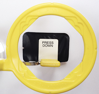
After image acquisition, the plates should be protected from ambient light image removal (Figs 6a and b). The exposed plates should not be left – even for a few minutes – unprotected from light, even when in a waterproof packet.
Ideally, when taking the images, the room blinds should be closed and the lights dimmed and light boxes switched off.
As the image is cleared in the scanner by light, the plate should be kept as dark as possible when image capturing and when being transferred to the scanner. To ensure this, the exposed plate should be kept in a light tight box prior to scanning and the scanner should be positioned in a dim room away from bright lights to enable plates to be loaded without losing image quality.
Special black boxes can be purchased that allow the plate to be posted in the top like a money box. Light cannot get in and the latent image will be safe until it is transported to the scanner. Alternatively, a dental appliance box or similar could be used. These are small, easy to clean, non-expensive and possibly already in the practice.
7. Exposure settings
PSPs have wide exposure latitude, which means they can give similar results when using a number of different exposures, unlike emulsion films which will be light or dark in relation to the exposure.
A number of test images can be taken using step wedges or extracted teeth to ascertain the lowest exposure that gives an acceptable enhanced image. This becomes the maximum exposure. Guidance should be sought from a medical physicist to ensure that exposure settings are adjusted when a practice moves to a digital system.
Other problems that can be encountered are with images that lack contrast and have an overall grey appearance (“greying out”) ({encode=”http://content.yudu.com/Library/A3ri17/IrelandsDentalJune20/resources/42.htm” title=”Fig 7″}). These are not images that can be enhanced by the computer to give more contrast. It is possible that the exposure is too low. If changes of exposure are being considered to give better-quality images, then guidance once again should be sought from your medical physicist.
8. Artefacts that mimic pathology. Unsharp Mask Subtraction (UMS)
Many of the image acquisition processes on digital systems are outwith the control of the user. These are intended to improve the image, but sometimes artefacts that mimic pathology can result.
Areas where there are high intensities, such as the base of a restoration or around dense bone, can result in a dark halo effect that can look like pathology. This is called “rebound artefact”. During processing and prior to viewing on the monitor, part of the acquisition process takes a blurred version of the image and subtracts it from the original. The blurred image is wider than the original and so when subtracted it can cause a shadow effect (Fig 8).
Image processing artefacts are becoming more subtle with more sophisticated systems. To minimise potential misdiagnosis, it might be prudent to consider other areas unrelated to the area in question and consider if the halo effect is present.
9. Viewing conditions
Many dental surgeries are bright, well-lit rooms. This can cause problems when reading images on computer monitors. It is important to ensure that optimum viewing conditions are obtained to allow accurate assessment of the computerised image.
The monitor should be placed in a dimly lit area where the light levels are approximately equal to those that would be normal in an overcast day or darker. A light level of about 50 to 100 lux, the SI unit of luminescence, would be acceptable. Many surgeries are lit to a level of 300 to 500 lux, which is too bright for optimum viewing conditions. The solution is to move the monitor or place a hood around it to cut down on light pollution.
10. Monitors
Test patterns that can be used to check monitor condition can be downloaded from the web: Society of Motion Pictures and Television Engineers (SMPTE) (Fig 9) and Technical Group 18 QC (TG18-QC).
These images should be captured and archived to be displayed at regular intervals, possibly monthly. These test the overall operation of the system and should be viewed in the same light conditions used in the surgery when viewing digital images. These images should be viewed full-screen for all tests. Whichever test pattern is used, the monitor should be checked for brightness, contrast, resolution and geometric distortion.
There are two squares on the test pattern, one black and one white, which are marked 5 per cent detail on the 0 per cent square (black) and 95 per cent detail on the 100 per cent square (white). Both of these should be distinctly visible and if not, the monitor settings should be adjusted until they become so. Most monitors cope better with the 95/100 per cent than the 0/5 per cent, but if the ambient light is kept low, both should be clearly visible. (Figure 9).
SSDs contain solid state materials such as amorphous silicon or amorphous selenium in their construction. There are two types of detectors containing either a charge coupled device (CCD) or complementary metal oxide semiconductor(CMOS).
The intra-oral systems generally have a flexible cable connecting the detector directly to the PC. Images are collected in real time and can be viewed on the monitor.
The sensors are bulky and rigid and compromised patients, children and the elderly will probably not deal well with SSDs. In comparison to conventional film or PSPs, the imaging area is smaller and, as a result, approximately three less points of interest will be captured by the direct digital sensor (Fig 10). Consequently, accurate positioning is essential to cover the area of interest.
The presence of the cable will not allow the teeth to be in occlusion during the taking of bite wing radiographs (Fig 11). A consequence of over-exposure could be pixel overload “blooming”, which can result in black banding on the image.
About The Author
Barbara Lamb qualified as a general radiographer in 1974 and, since then, has worked exclusively as a specialised radiographer in the dental field.
Further reading
Brettle D, Carmichael F. The impact of digital image processing artefacts mimicking pathological features associated with restorations. Br Dent J 2011; 211: 167-170.
Rout J, Brown J. Ionizing Radiation Regulations and the Dental Practitioner: 3. Quality Assurance in Dental Radiography. Dent Update 2012;39: 334-339.
Greenall C, Drage N, Ager M. Quality Assurance Tests for Digital Radiography in General Dental Practice. Dent Update 2014; 41: 126-134
Thomas B L, Davies J, Whaites E. Shall I Go Digital? Dent Update 2014;41: 314-326